2016-09-19

Lighting Calculations - Notes

Lighting Calculations, Round 2

Per the Wikipedia article...

1120 W/m2 of direct and indirect sunlight hit the ground.
1050 W/m2 of direct light.
43% is visble (400 to 700 nm)

luminous efficacy is about 93 lumens per watt of radiant flux.

Direct light = 97,650 l/m2 of illuminance.
Visible light = 41,989 l/m2

1 m2 = 10.7639 sqft

DWC: 20 sqft = 1.85806 m2
GB:  16 sqft = 1.48645 m2

Total required illuminance
DWC: 78,018 lumens
GB:  62,414 lumens

lumens per sqft:  3900

This means that we need around 8000 lumens per linear foot of grow space, since the spaces are 24 and 30 inches deep (respectively).  Four 2000 lumen elements, or eight 1000 lumen elements, would provide a sufficient quantity of light, plus we can balance out the wavelengths to provide a nice, full spectrum.

This would need to be repeated each linear foot, or 8 times, yielding around 32 or 64 (respectively) LED elements per grow space, to meet the lighting target.

A search on Digikey provides some ideas on wattage.  Efficiency will be between 80 and 140 lm/W. 80 lm/W buys us 1005 lumen elements, and 64 of those will provide 64320 lumens.  0.0125 (1/80) W/lm times 64320 lm = 804 watts for the smaller array.  Going with 140 lm/W in the search provided options for both 1005 lm and 1770 lm elements, so maybe we'll go with those instead.

Current electrical rate (assume the worst): $0.12047 / kWh

Assume 30 days per month, 12 hours per day of run-time.

Here are the array figures:

DWC:

  • 78018 target lumens
  • LED quantities:
    • 78x 1005 lm LEDs, or
    • 44x 1770 lm LEDs
  • Cost per LED (best price, rough-estimate):
    • $4.00 per 1005 lm element ($312.00)
    • $16.51 per 1770 lm element ($726.44)
  • Power Consumption:
    • 78 * 0.8 A * 9 V = 561 W for 78390 lm (139.7 lm/W)
    • 44 * 1.05 A * 12 V = 554.4 W for 77880 lm (140 lm/W)
  • Energy Cost (with above assumptions)
    • 78 element array = $24.33 / month
    • 44 element array = $24.04 / month
GB:
  • 62414 target lumens
  • LED quantities:
    • 62x 1005 lm LEDs, or
    • 35x 1770 lm LEDs
  • Cost per LED - same prices as above
    • 62 elements = $248
    • 35 elements = $577
  • Power Consumption:
    • 62 * 0.8 A * 9 V = 446.4 W for 62310 lm
    • 35 * 1.05 A * 12 V =  403.2 W for 61950 lm
  • Energy Cost (with above assumptions)
    • 62 element array = $19.36 / month
    • 35 element array = $17.49 / month

Commentary
The above figures are rough estimates.  Specifically, the energy costs are LOW-END estimates, meaning the final costs will be higher once losses in the AC to DC conversion are taken into account.  Also, the arrays are not necessarily geometrically optimal, meaning that 44 elements will not fit neatly into 8 linear feet of space (5.5 elements per linear foot).  A staggered design will be beneficial nonetheless, so this isn't necessarily a problem.

Output values for the lighting was taken from flux at 85 degrees C.  Lower temperatures should yield better light output (more efficiency).  Also, the test current was used, but max current ratings can be upwards of double or worse.  Higher current usage means less efficiency and higher power bills.

The costs above also do not account for: the LED drivers, wiring, heat-sinks, and LED mounts.

Return on investment will be realized when we save $50 / month on our groceries (really $43.69, but I'm throwing in a wild-ass-guess for the pump and aerator energy costs).


Further reading


2016-09-11

Project Update: Electrical Install

Before I lose access to parts of the porch, I have started running the electrical.  A snapped concrete drill bit today stopped my work before I could complete the first run, unfortunately.  Still, I managed to get quite a bit done.

The nearest receptacle is quite a bit away from the grow beds.  I have opted to run schedule 40 PVC electrical conduit from just above the existing receptacle, overhead of the porch door, and down to the right of the door (in the space between the door and the porch screen wall).  The conduit enters a 2-gang weatherproof box, where power will be delivered to a GFCI outlet.  From that outlet, power to the other outlets and the timer (for the lighting) will be drawn.  This means that everything downstream from the GFCI outlet will be ground-fault protected.

I had initially planned to use an existing single-gang electronic timer to drive the lights.  Upon further consideration and research, I decided that it would be better to use a standalone hardwire timer, one rated to significantly more wattage than the single-gang would have provided me.  I chose this one:  http://www.intermatic.com/en/products/timeswitches/electroniccontrols/24hour_7day/gm40ave.  I haven't had a chance to test it, since it's only installed and not wired.  The way I have it mounted, I can either run the return power back to the 2-gang box and manage an outlet there, or run a separate conduit down from the timer to a dedicated LED driver box.  I will most likely be pursuing the latter.

While I am trying to do everything to the NEC code (and I have the large, blue 2008 version sitting in my living room), I elected to leave the bottom plugs of the 2-gang box unsealed.  This was a wise decision, since I realized before this evening's run to our local home improvement store that the pump plug wire was not going to reach to the 2-gang outlet box.  I'll be running another conduit and placing an outlet right behind the IBC tank.

Please note that everything is being weatherproofed, so any stray sprays of water, splashes, or even a good soaking, should not cause any damage or death.  And, of course, the GFCI is there to help with that.  Everything, from the conduit to the wiring to the enclosures, is rated for wet locations, as defined in the Code.

As for the lighting, I have started doing more research on that again.  We recently purchased some LED flashlights.  The beams are adjustable, and with the focuser pushed all the way in you can see the actual LED element.  It's a single-lens array, square in shape, and the output is 350 lumens.  It is quite bright, and has caused me to reconsider just how much light my system actually needs.  I am thinking that it may be time to do some basic testing.  I have begun pricing out some components, and may make some purchases soon so as to get some experiments done.  What I would really like to do is set up a few makeshift grow chambers out of opaque plastic boxes (think the giant tubs for storing your junk in).  With these, I could set up three or four experimental lights and test a small tray of seedlings in each.  My control would need to be a similar tray positioned outdoors, for direct sun.  Unfortunately, I'm not sure I have either the time or the money to do this.  But then again, considering the thought of wasting money on the wrong lighting...


2016-08-16

Blueboard, Pump Installed

Slow going, but going forward.  I have installed the XPS Styrofoam board into both boxes.  See below:


The installation was extremely straightforward, and the nails went in quite smoothly.  I have cut, painted and installed a piece of 3/4" plywood for the pump-side of the DWC.  This is to support the bulkhead fitting that will supply the pump, though I am beginning to wonder if the XPS would have performed sufficiently well.  Nailed to both the lower and upper horizontal members, it is surprisingly strong between them.

The pump shelf is now also finished and installed.  I affixed two triangular braces to the underside of the shelf, which stabilized it nicely.  The shelf is cut to fit only the pump, and achieves that.  I positioned it with hopefully enough room between the pump inlet and the DWC bulkhead fitting to allow for adjustment of the pipe, since it won't be an exact straight line.  I may yet need to get somewhat inventive with the plumbing in order to get the pipe position I need; this may be a series of elbows (ugh - no), or some heat-bending (yes!).

I have drilled the hole for the DWC bulkhead fitting, and test fit the fitting in the hole.  All is well, except that with the extra rubber o-ring, there are barely two full threads to screw the fitting nut on.  I may have to leave the o-ring off, which may indeed be recommended - need to go back and check the Green Acres instructions.


I will soon be placing the two bulkhead fittings for the GB.  I haven't yet decided where.  I must also determine the final plumbing configuration for the GB drain; one option is to run one drain to the other, and both down a pipe on the head-end of the DWC (farthest from the pump).  Another option is to drain directly in the middle of the GB, thus ensuring equally good flow from either siphon.  Yet another option is to put the main drop in or near the middle, but then pipe it around to the head-end, for better nutrient dispersion.

I'll be cutting the PVC for the actual siphons soon.  I must also rip and cut to length the boards that will top of the box edges, where the liner will be affixed.  It too must be painted, hopefully the last thing I need to paint.


2016-07-20

Dry-fit Complete, Final Prep Beginning

I have finished as much of the painting as I'm going to do on the stands, the lower ramps, and the upper ramps.  The uppers and the stands each received two coats, but the lower ramps received one.  To help mitigate water intrusion from rain, I have decided to place 3 mil plastic underneath the lower ramps, so that it can be pulled up along the sides of the DWC tank.

To the right is a picture of the ramps, on the plastic, near final position.

If nothing else, the plastic will keep the ramps from adhering to the concrete floor.  I am not sure it will completely prevent water intrusion, but I also have no plans to completely or hermetically seal the plastic to the DWC, so there should at least be some free air movement.

Having placed the DWC on top of the ramps, and adjusting the whole configuration to sit roughly where it will probably be staying, I placed the stands into position.  Everything appears to be fitting together correctly.

After placing the upper ramps on top (not necessarily in their final resting positions), I noticed one of the ramps had twisted rather badly.  I may have to reduce the count to four ramps, which wouldn't be the end of the world.

I am generally pleased with the way the system is coming together.  I do remain slightly concerned about the headroom between where the DWC rafts will be, and the assembly that will support the GB.  All in all, there should be enough room to pull rafts in and out, complete with plants (assuming the plants are not very tall), or to pull out plants directly and harvest them one at a time.

Speaking of rafts, I finally received my new adhesive, but haven't had time to try it out.  That will happen soon.

Moving forward, I have put the GB onto the sawhorses for painting.  I'll need to procure more paint, but I'm tossed up between getting a gallon or a quart, considering that a quart is half the price of a gallon, and I may need two quarts to finish the job.

I'll soon be fitting the XPS Styrofoam to the DWC.  I need to make a decision, and soon: I must either double-up on the XPS for the end that will receive the pump plumbing, or I must cut and paint a piece of plywood for that section, OR I must put the pump inside the DWC.

My study of electronics is proceeding, slowly.  I now have enough knowledge that I can start to make some more intelligent explorations into available components.  I highly doubt I'll have the expertise in time to assemble my own current-source, let alone outfit it with all the safety features one finds on such devices as to be available in Digikey's catalog.  This is partly because I am rapidly approaching an area of the topic where differential equations will be required.  I didn't fare well in that course, and since diff-eq requires a solid grounding in the calculus, I am engaged in reading a calculus book.  So, while I will continue both the calculus and the electronics studies, I will need to concede that my know-how will be limited to simple resistive circuits, powered by robust and commercially available supplies.  And that's fine!

As far as the lighting choices are concerned, I must also concede a sort of defeat there as well.  But not really...  Instead of building out full arrays from the get-go, I plan to build some test assemblies and try some plants under them.  This isn't really ideal, but unfortunately it's the best I can do under the circumstances.  I just really can't afford to buy ten massive LED components at nearly $20 a piece, and find out I was wrong about them.  This isn't really a bad thing, though.  This is another opportunity to explore and experiment, and obtain a good working result that I can expand upon.  What I have to do now is resist the temptation to purchase (at around $500) a full spectrum quantum sensor from Apogee Instruments.  Theirs will work with LEDs and provide the necessary data to quantify the actual light output.  Of course, maybe that investment wouldn't be entirely unwise...


2016-06-26

Foamboard and Paint

I have finished first-coating the stands, and the lower ramps.  The upper ramps are almost completely second-coated.  See below:

 The paint is going on well enough, but I fear one gallon will not be sufficient once I get to the upper growbed.  The stands are extremely annoying with all their nooks and crannies.  But once painted, it will be done.  I am a bit concerned about the feet of the stands, and the lower slants.  For the former, the notion of water intrusion (as the porch gets wet during storms), and for the latter, I fear they'll "glue" themselves down to the floor after being there for 6 months.


I returned the two undamaged 1/2" foam panels to the home improvement store today, and procured two "blue board" foam sheets.  The key difference is: this foam board is extruded polystyrene (XPS), rather than the white expanded stuff I had purchased previously.  The foam is much denser, doesn't flake, and is reportedly waterproof.

I tried to get the store to order the 2" thick foam I needed, but to no avail.  It seems no one carries it.  I even tried looking for DWC suppliers, but again came up dry.  I'm really at a loss to know what people use, if they don't use completely inert Styrofoam.

Not all is lost, though.  I purchased enough XPS to experiment, and ordered a specific adhesive from the local box store's website.  The adhesive is called Eco-Bond, and reportedly (for the "Farm-Safe" variety) is completely non-toxic, hypo-allergenic, etc etc etc, no evil chemicals, no distillates, waterproof, etc etc etc.  Certifications abound.  Seems too good to be true, but we're gonna give it a try.  Worst-case, I'm out $13.  The goal will be to laminate two or three (or maybe even four) sheets of XPS together, to form a decent DWC raft.  I'm still undecided whether or not I should pre-drill or pre-mark the hole locations, and then glue around them, or else just clue the whole board with lots of beads of glue, and hope I got good enough coverage to avoid splitting during use.
 

2016-06-13

Paintwork and Rafts

Painting

I have begun painting the various assemblies for the project.  I managed to find a good exterior-grade latex paint with low-VOC and relatively waterproof.  I'm putting two coats on for the serious wear-areas (any place that will be subject to the occasional water splash or mechanical interaction.

So far, I have only mostly completed the DWC tank.  It's one coat on the top-facing surfaces away from completion, and I will probably only double-coat the sections that won't otherwise be covered by or in contact with other materials.  Due to limited space on the porch, I'm playing musical-components in an attempt to avoid running out of room while painting and assembling.  Thus, the DWC is now sitting roughly where it will stay.


The color white was chosen arbitrarily....and partly to save time in the paint department.  To date, I've gone through nearly half of my one and only gallon.  The second coat does require less paint, luckily, and the GB will be less area to paint as well.  I must also paint the stands, the stabilizer boards, and the ramps for the DWC.  I have one coat on the GB ramps already (which I call "slants" in other posts).

Rafts

I was going to also cut apart some of my rafts today.  Then I made an unfortunate discovery.  The FAO manual mentions making sure that the polystyrene one uses for the rafts be of a food-grade (or food-safe) material.  OK, that makes sense, especially for the fishes.  I looked at the 2" thick sheet that I had already hacked up into a non-returnable state: contains flame retardant.  Fuck.

According to 365 Aquaponics, blue board insulation, or extruded polystyrene (XPS), is the best.  I had purchased expanded polystyrene, which is not recommended (it evidently disintegrates, among its other attributes).  I hope the blue board will also be sans chems, as others have reported that any chemicals within the polystyrene will leach out additives and these additives can be harmful to the fish (to say nothing about us humans).

I'm now going to engage in a brief search to locate possible sources of food-grade XPS.  I'm hoping that home-improvement stores will NOT be the only option.  If they are, I'll have to either find 2" stock or figure a way to adhere two or more thinner pieces together...while keeping it food-safe.  Fully cured polyurethane is one possible route, as (reportedly) once it's fully reacted it thereafter becomes inert and safe to handle.  It should also be waterproof.


2016-05-25

Nearing Grow Bed and DWC Completion

Status update here:

The grow bed box and DWC tanks are nearing completion.  I have affixed the 3/4" plywood to the bottoms of each box, after having pre-drilled and countersunk holes along the edges of the plywood.  I suppose it was not strictly necessary, but then the plywood was also not going to be tied to anything else and so would have been floating free.  I can always disassemble the boxes, even after the liner is installed, but I'm figuring that they will stay together until they literally fall apart.

The two boxes, upside-down
In the (unfortunately messy) image above, the two boxes are seen, the larger DWC tank sitting on top of the GB, and both upside-down.  On top of the DWC is the 2" foam board for the rafts, already cut to width but not yet to length.  I have given it 1/2" of clearance on either side of the design size of the tank.  Hopefully that will be enough.  I have enough 2" board left that I could play around with non-floating rafts.  I believe I read about these in the FAO AP publication, and they sounded interesting, albeit with their own brand of downsides (like everything else).

The beds had been sitting on the sawhorses (right side of the image) until a few nights ago.  I was able to lift the GB down to the ground myself, only by virtue of exploiting the physics of balance.  After the plywood was attached, each box gained considerable weight.  Further moves will require the assistance of at least two more people (unless I can find just one rather burly individual).

Roughing-in the stands
On the porch, it's a game of musical junk.  There are some outstanding projects that need to be completed, and for which materials remain (such as all that white junk on the floor).  Also, I have a few too many pieces of lumber, so there will be a return to the home-improvement store in the near future.  Once we relocated the DWC, however, it was then time to get the sawhorses out of the way and trial-fit the three stands.  You can see in the photo to the right the sands and the slants.

I had intended to rig up a jig to ensure clean, consistent cutting of the slants, and also purchased enough lumber to cut individual boards for both top and bottom sets.  As it turned out, a single board made two very nice pieces (thanks to the law of similar triangles), so I cut my board requirements by half.  Second, making a jig became extremely difficult due to the lengths involved.  I eventually settled on using as much of the jig as I had already assembled (which was a glorified board-holder, and not a very good one at that), and marking and free-handing the circular saw along the cut.  For the most part, the cuts went well.  I rarely strayed from the line, and when I did it was because the line was nearly invisible on some of the pieces (curse of pencil on PT lumber...I used a Sharpie for the board that followed).  I tested one of the pieces with a level directly on the porch floor, and to my exuberance the angle evaluation and cut was good!!  So now we should have nearly level grow boxes.

Next up will be purchasing the liner, the paint, and the marine sealant for the bulkhead fittings.  I am still working on the lighting, and have finished most of the reading I had started on the subject.  I'll discuss my findings in another post.  I haven't yet planned where the fittings will go on the GB, since I must account for the 6" diameter media guard.  I was thinking of locating them near the back of the unit, so as to keep the plumbing out of the way of the DWC, but it occurs to me that the DWC is wider than the GB so that point may be moot.  In any case, once the liner is installed and the GB and DWC tanks are fixed in place, I can start doing leak and siphon testing.

Rockin'....

2016-05-19

Production Siphon Experiment 2, and (Dis)regarding the Venturi Effect

After the dismal failure of my own damn reasoning, I worked on some revisions.  The target drain pipe size for the system will be 1.25" diameter.  I performed a test with this pipe, plus some 0.75" pipe to test some more relay siphon ideas.

The basic configuration I used was 1.25" for the below-bed siphon and drain pipe, but 2" for the standpipe.  This was partly on a whim.  I also experimented with a 1.25" standpipe.  The 2" worked significantly better, especially draining into the 1.25" lower siphon pipe.  It was as though I had simply moved the "funnel" that is commonly used in other configurations down to below the grow-bed.  I suspect the funnel action here really has nothing to do with the Venturi effect.  More on that below.

During the tests, I ran the water pump and cycled water between my test tank (a 20 gallon rubber-like plastic container I picked up for cheap) and a makeshift sump tank (a sufficiently large galvanized tub - from whence I bought it, I have no idea).  This provided a great opportunity to both test the pump at the likely head-height, in the production plumbing, and to save some water.

The 1.25" standpipe produced a very undesirable result: as water spilled into it, it formed a vortex which was maintained indefinitely.  The vortex evidently allowed sufficient water to leave the tank, and prevented siphon formation.  The 2" standpipe did not appear to suffer from this problem, and worked repeatedly without fail.

Apropos: my current bell is a 6" diameter PVC pipe, covered with plastic kitchen wrap and "sealed" with tape.  The wrap provides a sort of window into the inner-workings of the siphon.  My next available bell size is 3", which is too small to work with the 2" pipe and adapters.  I am hoping that 4" pipe will offer sufficing inside diameter.  The store does not seem to carry 5".

While watching the 2" pipe, I noticed that the flood of water down to the reducer fitting caused enough turbulence and sufficient restriction of flow for a decent blockade of water to accumulate, and thus the siphon would shortly follow.  I decided to try relaying in the 3/4" pipe I had installed in the same tub.  I used a 1.5" wye fitting, normally used for waste-water collection, and (due to a lack of 3/4" fittings) drove the 1.25" plumbing into the wye at 45 degrees.  The 3/4" pipe went straight down into the fitting, and the exit was directly below.  Appropriate adapters were used to deal with the size differences.  The exit piping was unfortunately a little too short: it ran straight into the sump as I tried to lengthen it.

Unfortunately, it didn't work.  The key problem was that there was simply too much turbulence at and after the wye for a good seal to form.  Even when the 3/4" standpipe was cut so that it was very close in height to the 2" standpipe, there was insufficient suction to start the 3/4" pipe.  I suspect this issue could be averted if the 3/4" was upstream from the 2", and the 1.25" pipe had sufficient horizontal length downstream of the 2" standpipe to ensure a good blockade of water.  I plan to retest, using the other 2" bulkhead fitting I have, once I have some 4" pipe.

Regarding Venturi

I am beginning to suspect that at the pressures and water velocities we're dealing with, the Venturi Effect is a negligible effect at best when we examine the funnel-style standpipe.  I'd like to propose another hypothesis: mass of water.  Let's suppose we have a 5" length of 2" diameter standpipe.  Water begins to flow over the top circumference and down the inside faces of the pipe.  Let's assume the water flowing down is 0.1" in thickness.  Let's freeze this scene as the water reaches the bottom of the standpipe (which is also the top of the 1.25" siphon drain).  For a 2" pipe and 5" of length, that's about 3 cubic inches of water.  Were we considering the same 0.1" thickness of water inside the 1.25" pipe alone, that would equate to about 1.8 cubic inches of water.  In other words, the larger standpipe provides a deluge by virtue of its geometry alone.

Dividing the 2" pipe's low volume of water by the 1.25" pipe's cross-sectional area gives us the result that the same volume of water would occupy 2.43" linear inches of the 1.25" pipe.  This, I believe, is the reason the siphon starts so easily with this configuration: that much water flooding the pipe is significantly more than a 1.25" standpipe would have supplied, thus a water blockade can form and induce a siphon.

The picture here attempts to illustrate the example from above.  The siphon is in red (2" standpipe, 1.25" drain), water is in blue.  The drawing is to scale.  The water on either side of the standpipe represents 0.1" of thickness.   Realize that the water is actually coming down around the entire circumference of the standpipe opening, and so is much more voluminous than what I can easily illustrate.  The water shown leaving the drain pipe (which is pointing down) is the equivalent volume as what is entering the standpipe.  It, too, is to scale.  As you can see, a relatively small volume of incoming water becomes a relatively large volume of draining water, and should saturate the pipe volume sufficiently to start the siphon.

Were we to use two 2" pipes, or two 1.25" pipes (that is, the same size between the standpipe and the drain), we must then hope that the water level continues to rise sufficiently to eventually saturate the siphon.  In the meantime, there would be physically little to stop the water from simply draining through without accumulating.  Thus, I suspect the Venturi effect is of little value here, and that the geometry of the pipes provides the most potential benefit.


2016-05-15

Progress, and a Failed Experiment

Today I was able to procure many additional materials: plywood, polystyrene panels, 2x4s and 4x4s, plus some plumbing supplies for further experiments.  I assembled the three grow-bed support frames.  I had to obtain a larger container to carry out the siphon experiments.

As I had mentioned in my last post, I had a crazy idea:

A miserable failure - do not repeat it!!
Yes, this is a two-stage inside the same bell.  IT DOES NOT WORK.  This is why I take notes on these things...it's just too bad I didn't actually re-read them before attempting this hair-brained idea.

Why does it fail?  The small red pipe feeds directly into the large main pipe.  There is no way enough water can flow into that massive blue down-pipe to form a siphon, therefore the siphon simply never forms.  What made the original 2-stage experiment successful was that the starter siphon formed a full and fast siphon. With the additional water being pumped into the larger out-piping, there was sufficient volume to start the larger siphon.

That is not the case with the above illustration.  What you see above is simply a slow flow into a very large pipe, which would happen even without that extra red pipe sticking out the side.  Without an actual siphon forming with the smaller pipe, there is insufficient water flow to trigger the main siphon.

Some other bad points about the above design: it's huge, it requires a very large diameter bell (which equates to an even larger media guard - bleh), it doesn't work (as previously mentioned), it requires many more fittings than its worth, and so on.  I will be trying some more experiments soon.  Namely, I want to see if a 3/4" starter siphon will trigger a 2" main siphon.  If it does, my next experiment will test two 2" main siphons with the 3/4 starter.  I can also modify the diameter of the out-piping, to help ensure the flow is sufficient to trip the other siphons.  The catch is that the smaller the out-pipe, the less flow it can handle, so there may cease to be a reason to run 2" siphons.

2016-05-11

Bulkhead Fittings and Siphons

I have purchased a small selection of bulkhead fittings from US Plastics, an online supplier of those and evidently a large variety of other plastic-related items.  I am currently gearing up to procure another round of supplies, at which point I will be very close to the point of being able to fill the system with water.

Since I had to purchase fittings, it seemed like a good time to do some calculations and make sure I was sizing the plumbing appropriately.  I assume a pump rate of 800 gph (it's a 1000 gph pump, but I am attempting to account for head loss).  I can't seem to find the calculations (they must be in another spreadsheet), but for the moment I am assuming that the media will occupy about 30% of the GB space.  The GB's max operational capacity is approximately 100 gallons.  Thus, we will suppose 70 gallons will filter into the GB before the siphons start.

Given the above, the anticipated static fill time (the time it takes to fill completely before draining starts) should be about 315 seconds.  A 1 inch diameter drain pipe should pull the water out of the GB in about 200 seconds.  Figure in the constant fill rate, and the drain time jumps to 547 seconds (we'll call this the dynamic drain time), meaning it would take far longer to drain than to fill.  At 1.5 inches of drain diameter, we should expect 124 seconds of dynamic drain time.  That's better.  At 2 inches, it should drain all 70 gallons in about 59 seconds.

Now, I can only cut these holes once, and I am slightly concerned that the length of the bed will cause one side to become more stagnant than the other, should I place the drain in one corner.  The alternative is therefore to add a second drain.  Two 1.5" diameter drains equals one 2.12" diameter drain in drain area, so the dynamic drain time would be around 52 seconds.  Two 2" drains (equivalent to one 2.83" diameter drain) will reduce the drain time to 27 seconds.  These times do assume sufficient out-piping, which means I would probably need to enlarge at least a portion of the pipe running down to the DWC.

Whether or not I really need the second drain is up for debate, but by at least installing the bulkhead fitting now, I can always add the actual drain later (and otherwise just plug the hole if it need not be used.  If I do go with the larger size pipe, or two of them for that matter, I will very likely need to contend with a siphon start issue.  Thinking back to the pull-start siphon I experimented with several months ago, I decided it might be good to find a way to build that in.  Putting two bulkheads next to each other, however, did not seem like a good idea, and the loss of GB real-estate was becoming bothersome.

One potential solution, which I will be experimenting with as soon as the fittings arrive, is to put the start-pipe assembly above the bulkhead, rather than below it.  In concept, there would be only a single pipe and single bulkhead fitting.  The pipe would tee immediately above the fitting, and proceed up at full diameter and out at the start-pipe diameter (1/2" most likely).  The start pipe connection would do a bend and then run parallel to the main drain, terminating just below the top of the main.  The start pipe would therefore set the max water height in the GB.

Two siphons should not pose any special difficulty, as long as they are drained together.  If the main (pull-started) siphon is closest to the out-pipe, and the secondary siphon connects into it just before the out-pipe, the secondary siphon should get pull-started by the main siphon.  That is, once the main siphon trips, it should pull sufficient vacuum on the drain plumbing to forced the second siphon to start.  The effect will be a three-stage drain: start, primary, secondary.

It may be better to put the primary siphon upstream of the secondary, but my only concern is that the long horizontal run will cause problems for primary siphon start.

Regardless of how the siphons are started or how fast they flow, this action has an effect on the DWC tank:  given the dimensions of the DWC, a 70 gallon ebb-and-flow will equate to approximately 5.6" of rise and fall.  Consequently, the pump will need to gather water from as close to bottom as possible.  It should be noted that this height changes is slightly more than 50% of the maximum water height for the DWC.  Should it be determined that less water is required in the GB to trip the siphon, then this percentage will be reduced accordingly.  (For instance, a 50 gallon ebb-and-flow will equate to a 4" rise and fall.)

I plan to position the water pump outside the DWC, piped so that its inlet it always submerged.  I may need to find a decent filter material to keep debris from entering the pump.  One of the bulkhead fittings I acquired is intended to go through the wall of the DWC.  This is mainly to ensure that the pump can be properly primed before starting, as it is not self-priming.

Testing will hopefully commence soon!

2016-05-05

Lighting Research - Preliminary Studies: White versus Red/Blue

I've been doing quite a bit of reading about the lighting requirements of plants.  I'll provide some details on my findings, plus references, in another post.  For now, some notes.  My goals are to build LED lighting assemblies that will provide adequate and appropriate light for my plants.  As there will be a variety of vegetables, plus fruiting plants and hopefully some root-plants, the lighting must be able to accommodate them all.

I investigated HIDs and fluorescent fixtures, and ruled both out as too costly in terms of setup and upkeep.  The former are power-hogs.  The latter's bulbs reportedly lose value after 6 months and require replacement.  LEDs to the rescue, then!  But, it's not so simple.

Firstly, manufactured LED assemblies are horribly expensive.  Second, the majority of them are red-blue fixtures.  Some also incorporate green.  I did a great deal of search about the best growth spectrum, the typical spectra for chlorophyll, and eventually found myself on a very detailed site regarding photobiology.  Here's what I have so far...

Chlorophyll-1 and -2 do indeed absorb rather specific portions of PAR light.  One takes the majority of its energy from around 450nm, the other from the 640nm area (very roughly, don't count on those numbers AT ALL).  However, their precise absorptance spectra depend on the solvent in which they are dissolved, if considered in vitro.  When one considers the effects of PAR spectra in vivo, it has been observed that a very wide range of the 400-700nm wavelengths are indeed absorbed.  These are not necessarily absorbed by the chlorophyll itself, but could be absorbed by accessory pigments and other chemical processes within the plant.  Furthermore, the presence of other proteins and chemicals either attached to the chlorophyll, or within close proximity to it, will affect (sometimes to a great degree) the spectra that the chlorophyll can and will absorb.  We cannot rely on in vitro data alone to build our lighting, as it does not accurately characterize the actual operating conditions of chlorophyll.

Some plants also make specific use of the far-red region of the spectrum.  This is evidenced by phytochromes, namely Pr and Pfr (for the red and far-red spectra).  The two convert to one another in the presence of the right light, and if I remember correctly Pfr converts without light input to Pf.  The relative quantities of these two phytochromes determine the expression of certain traits, such as the straightening of plant parts.  But the key take-away is this: we cannot alone rely on the spectra relevant to chlorophyll to determine the appropriate lighting.

Given that this will not be a monocrop, and given that the sun's spectrum in the PAR region is generally flat (as apposed to the spiked spectra for chlorophyll-1 and -2), it becomes evident that focusing on only the blue and red spectra will not be for the best of the plants.  In other words, white light with a fairly even spectral distribution will be the optimal light, with what limited information I have about the goings-on inside the plants themselves.  While it will certainly be sub-optimal from the point of view of chlorophyll - that is, I am technically "wasting" power on light that isn't immediately absorbed by the chlorophyll - it will also be the kind of light the plant has evolved to expect.  Given the number and variety of inner-plant processes that we either do not know, or do not understand, it is possible the spectra-restricted (red/blue) lighting is itself deficient, and therefore wasteful.

Many questions remain:

  • How much light, in terms of PPF per day, will the plants require?
  • What will happen if too much light is provided?
  • What will be the best LED light source for the spectra chosen?  Will I need to augment that spectrum with additional, spectra-specific LEDs?
    • That is, most of the white LEDs I've surveyed to-date (all from Cree), tend to show dips in the spectrum after blue, but before yellow/red.  This probably means emission of the green spectra is greatly reduced.  I would have to compensate with additional green LEDs, but only if that really matters in the end.  It's possible it does not.
  • What should be the minimum and maximum distances for the light sources from the crops?
    • On the DWC, there will be no choice
  • Will the even, consistent lighting prevent fruiting?  If so, will it be necessary to implement additional lighting (in specific spectra) that can be triggered on an as-needed basis?
  • If spectra-specific lighting is required for fruiting, will it cause non-fruiting plants to bolt?
The math also looks like it will be fun.  Lots of 10-to-the-very-large-number exponents.


2016-04-27

Updated Layout, Electrical Draft

So here it is, an updated layout with an IBC for better representation, and the latest incarnation of the GB+DWC setup.  The reconfiguration of the grow structure has allowed me to regain some space closest to the patio doors.  The electrical run is shown in pink.  There should be about 15" between the grow structure and the step that leads up into the patio door, meaning there is more than 15" between the structure and door itself.


The area on the floor in green is more than 2 feet away from any wall or barrier.  The yellow areas are within the 2' range.  Thus, I can move the grow structure even further away from the door, though not terribly much more.

I have yet to spec the actual components for the electrical.  Right now I need a minimum 3 outlets, all GFCI-protected.  I am thinking of putting a main cutoff on the left, on the pipe run originating outlet box (the grey box lowest to the ground to the left of the door).  The outlets will need to be wet-location protected.  I would also like to integrate a timer into the build, for the lighting.  I have one which isn't being used - it used to run the pool pump (but the pool is gone...for now).  It would fit nicely in on the left or right.

I'll also have to see how much wire each of the electrical appliances comes with.  The water pump should be no problem, I think it came with a ton because it's submersible.  The air pump, on the other hand, may be another story.  That said, I will need to experiment with the length of the air hose to see how it affects pump efficiency.  If it's not terrible, I might be able to store the pump close to the outlets and run longer air lines.  One way or another, I'll have to come up with a way to protect the air pump from the elements.

I am currently in the process of researching LED lighting options.  It looks like a DIY build will be required, if I want any reasonable amount of light output.  That said, I'm not sure how much light I need.  There's only indirect light back there, so some direct LED is a minimum requirement.  Having it be DIY also means I'll need to properly store and protect the LED drivers and any power transformer equipment...gaaah!  IP66 anyone?  Perhaps rated fixtures are not such a bad investment after all...especially if I could find some on eBay.  Or perhaps I should build or attach a weatherproof box to the back of the grow bed?

If you're wondering why no HID or fluorescent, I simply don't have the headroom for the lower tank, and really not for the upper tank either.  I'm not even sure how I'm going to mount the LEDs for either.  But an LED bar should be no thicker than a T5, when it's completed and mounted, and should put out significantly less heat.  Moreover, and the main reason, it should cost significantly less in power.  That's a big deal.  That, coupled with low voltage (always a nicety around water) and the potential ability to encase a good portion of the electronics in epoxy (waterproof!!), makes LEDs very attractive.

Modeled, but not shown in the picture above, is the sloping porch ceiling.  The long horizontal electrical pipe running over the patio door is situated just below where the ceiling meets the wall.  That's also the highest point for the ceiling, so perhaps you can appreciate the headroom situation.


2016-04-25

Grow Structure Design Update

On and off over the last couple of months, I have been toying around with different ways to support the grow bed and DWC/sump.
Various ways to put the GB on top of the DWC.


 There are two key problems I have to solve:
  1. The bottom of the grow bed must provide sufficient clearance to allow both functional DWC access, and to ensure the DWC lighting will not be too close to the plants.
  2. The patio where the system is to be located has a very unfortunate slope: approximately a 1 5/16 inch drop over an 8 feet run.
Point number 2 provides a most amusing problem.  The DWC tank is 8 feet long.  Left unchecked, one side of the DWC tank (and, of course, the GB) will be 1 5/16" lower than the other.  Since the pump will be located on the high-side of the tank, this is no bueno.  I have toyed with some options for dealing with the slope.  The first, and so far still the best, is to cut several ramps that will act as combination joists-and-slope-correction.  Another alternative was a set of wedges, cut so as to be placed at regular intervals along the bottom of the DWC tank.

Mounting the GB above the DWC is also an interesting challenge.  As I mentioned above, the DWC needs to remain accessible.  I figure I should keep a minimum 12" between the top of the DWC and the bottom of the GB supports to ensure good access (meaning I can get my boards in and out, with large plants, without crushing or destroying anything living in the process).  To complicate things, I also cannot have the GB situated too high, or it will become difficult to plumb it and to access it during actual operation.  Due to the slope problem, the DWC tank will also be situated slightly off the floor, thereby reducing the already limited clearance between the DWC and the GB supports.

Another goal is ease of build: I don't want to mortise if I don't have to, as it's a PITA.  Considering the weights involved, I also don't want anything potentially compromising the precision of the legs.  My calculations put the DWC tank weight around 1,000 lbs when filled.  The GB will probably be in that ballpark, as well.  Much of the GB's weight will depend on the weight of the media.  I'm planning on going with Aquarocks: a sort-of Hydroton alternative, where if Hydroton and lava rocks got together, Aquarocks would be their baby.

As if this all wasn't enough, the patio slope presents a bonus problem: the legs of the GB stand will be tilting by approximately 0.8 degrees.  Over the 3.5" width of the leg, this equates to one side being a little more than 1/32" higher than the other.  If the legs are 30" long, the top will be displaced by roughly 0.41".  Lateral force due to the 1,000 lbs load should come to something like 13 lbs, so it will be as though there is someone pushing against the legs with 13 lbs of force at all time.  Now that I have that written thus, I may be reconsidering my plan to not slant the feet of the legs.  My only hope - and perhaps I should check a physics book on this - is that the load will at least be distributed among 6 legs, so 2 lbs lateral force per leg.  Also, given that there will be 998 lbs of downward force, perhaps this is really all moot.

Here's the current draft plan, plus a look at how the tote squeezes in on the patio:
The build: notice the purple slants.
They're there for a reason.

Large, beastly recycled IBC tote, located where it needs to go.
The one problem with the tote is that it forces the "near-end" of the GB/DWC out away from the wall, breaking the clean lines that had always dominated the system.  But that's fine.  A small sacrifice for an extra 130 gallons of capacity.


2016-04-23

Build Update 2016-APR-23

Today we purchased a recycled IBC.  This will become the fish tank in the now-modified build.  More modifications to come.  The tote itself was available with a new bottle.  It was slightly more expensive, but since it has never been used we can be assured there should be no contaminates lingering.  I'll wash it out all the same.

The tote is a 330 gallon, which is about 130 gallons larger than the tank I had originally spec'd.  I'll have to use a SLO to deal with the waste accumulation on the bottom, but I'm hoping that will work OK.  An alternative would be to use the bottom drain itself, but I hesitate to do that, partly because it's facing the wrong direction.  The tote is also shorter than the cone-bottom tank, and since it's free-standing it was also about 1/4 the cost (i.e. no stand required).  I may place it on some PT 2x4's just to get it off the ground, since the back porch gets quite a bit of rain-water on the floor.  It's really just an accumulation, but also quite an annoyance.

I built the two frames (below) a few months ago.  Unfortunately, the project has stagnated due to lack of funds.  On the bright side, this has given me time to reconsider the fish tank (which is why it's now a tote), and time for the PT lumber to dry out.  With it dry, it will be easier to paint.  I still have to purchase and cut the PT plywood, and have been reworking the grow bed stand.  I am hoping to fix a few design concerns I had, and make it so that both the upper bed and lower DWC tank can be properly leveled.

The lumber, all cut and labeled


More pre-cut pieces.


The two boxes, sans bottoms.


2016-02-02

Build Revision - Media plus DWC

I purchased a copy of the Green Acres Aquaponics' manual, which describes both the basic knowledge required for aquaponics and their specific build projects.  It was a good read.  I skipped a good deal of the basics, having already obtained them from multiple other sources.  But their build was fascinating.  They basically have a compact system that sports a small-ish fish tank (100 gallon I think), a roughly 4-ft by 4-ft media bed, and a 4-ft by 8-ft sump and DWC tank.  You can get all 8 feet of sump to work as DWC if you have the floor space available.

This turned me on to something I had been mulling over since I first designed my prototype: how to make use of that blasted sump.  One idea was to add media to it, to improve the bio-filter.  But without growing plants, it seemed like a bit of a waste.  The GAA manual also demonstrated how to use a specific liner for their builds, and that opened the door to this:


This is a media bed over a combination sump/DWC tank.  The upper bed is 2' by 8'.  The lower is 3' by 9'.  Since the entire system has to fit in a very small footprint on my back porch, and will already require artificial lighting, I'm planning on simply adding additional lighting to the underside of the media bed.   The last foot or so of the DWC will either get lighting somehow affixed over it, or be partitioned off and used as a place to add chems, etc.  While most publications seem to favor putting the pump in the sump tank, I still think I'd prefer it to be outside the tank for ease of access.  Guess we'll see how everything fits on the porch.

The GAA build also sported a radial flow clarifier.  The clarifier fed directly into the sump, and the media bed drained into the sump via bell-siphon.  I had originally started planning one into this build, but then changed my mind after figuring the media bed would probably provide sufficient filtration of the particulate matter.  That said, I can always add a clarifier later.  My idea for the clarifier was to set it high enough that I could set the sludge drain to empty into the media bed.  After all, the media bed was going to get straight fish water one way or another.  Theoretically, managing the plumbing such that the outlet for the clean water and the outlet for the sludge would be at the same elevation ought to give me two outlets with two different purposes, from the same device.  This will be something worth experimenting with in the future.

I have yet to price out the lumber for the above build, and the build requires a little further fine-tuning anyway.  If the total price comes out below the original build, I think that'll be a great value.  If higher, it will probably still be worth it for the fact that we'll more than double our growing capacity (since DWC gives you a much higher plant density than what you can achieve with media).  If significantly more - which I'd have a hard time believing - then we'll reassess just how important the DWC tank is.

Some things that this build doesn't give me: I won't be able to control the media bed flood and drain rates as much as if they were two separate beds - this means less opportunity for experimentation.  The DWC might suffer from particulate accumulation without the clarifier; we'll see.  The top of the media bed is quite a bit higher than the original plan called for - or at least I think it is...I haven't measured yet, but it's at around 40" at present and I don't want it to go much higher.

I'd love to have the space to spread things out, rather than planning to bend and stoop for DWC plant access.  However, this is a trial build after all and hopefully, with sufficient lighting, we'll get a good return.

2016-01-21

Relay Siphon - Theory and Practice

I have done some additional experiments with the relay siphon, and am pleased with the results.  Using a 1/2" diameter control siphon, I was able to start the main siphon in a very short period of time.

Here are some numbers:

Relay Siphon Test
1" drain, 3/4" main standpipe, 1/2" control standpipe
Fill Rate0.01449275362in/sec
time to 1/2" spillover195sec
height at 1/2" spillover5.326086957inches
volume at spillover13257.96562cm3
main siphon start time14seconds
main drain time17seconds
main drain rate779.8803306cm3 / sec


Most of these numbers are approximates, since the timer is human-operated and the measurements are not exact.  What we can be certain of is that the relay does actually work.  The 1/2" spillover height is the water level where the 1/2" control standpipe begins experiencing water flow.  The siphon start time is the time between when the control siphon starts and the main siphon starts - that is, the control siphon operated for 14 seconds before the main siphon began to pull water down.  From the time the main siphon operated to the time it finished was 17 seconds.  Note that during this time, the control siphon had lowered the water level as well, but by only a very small amount.

Here's a picture of one of the other relay tests:

The presence of the trap does not necessarily help nor hurt the control siphon.  It does cause air to be trapped in the control bell, so the water level does rise quite a bit higher than without the trap.  The above picture shows the 1/2" control (left) feeding into the 3/4" tee from the main (right), into a 90 and down a 3/4" drain pipe.  The drain rate on this setup seemed slower than the 1" drain pipe, but unfortunately I didn't have time to pull any timing numbers.  But again, this test was primarily about the function of the relay.

To ensure the water level was slow enough not to trip the 3/4" standpipe, I capped the control pipe and let the water rise.  As expected, there was insufficient flow and insufficient back-pressure to trigger the 3/4" siphon.  Uncapping the 1/2" standpipe caused a flood of water into the drain, which then triggered the main siphon, thus demonstrating that sufficient flow from the control was all that was necessary to induce the main siphon.

Replacing the bell on the control siphon allowed it to function as designed: by starting its siphon at sufficient water height, and providing sufficient flow via siphon-action alone to trigger the main siphon.  I was able to watch the main siphon start using my snorkel bell (described in an earlier post).  It would start several seconds after the control started full siphoning.

While a single large main siphon will certainly draw water out of a grow-bed quickly, I could see this mechanism also finding use in long grow-beds where the risk of poor circulation may be significant.  You should, in theory, be able to tee-in a number of main siphons and have them trigger off of one control.  Once one of the main siphons starts, the flow should be great enough to start any remaining main siphons that did not start from the control flow alone.  I'd like to experiment with this in the future.

All this fast draining potential has me asking another question, however - one that I don't readily see much information on in the literature I've read to-date: how long should plant roots be exposed to water before the grow-bed is drained (or air after it has drained)?  If it takes an half hour to fill the bed, and 60 seconds to drain it, the roots may be exposed to air for at least 15 minutes before the water level is high enough to touch their tips.  I'm hoping there is other literature out there, especially among the hydroponics community, that addresses this.  The closest thing I think I've seen to a number is with the timer-based flood-and-drain systems: 15 minutes of fill time, 45 minutes of drain-and-empty time.

More work to do!

2016-01-18

Two-stage (Relay) Bell Siphons

I was considering today how to deal with the flow-rate problem for siphon-start, when an idea struck me.  I suspect someone has thought of this before, but a short web search didn't turn up anything fruitful.  There is one fellow I know of that does something similar: he has multiple large grow-beds on a slope, and synchronizes their draining using a 55-gallon drum.  There's a video on YouTube about it.

How about for smaller grow operations?  Let's suppose you have a fairly large grow bed.  First problem: the bed will fill very slowly, so the rate of height-gain of the water may not be sufficient to trip a large-diameter siphon.  Second problem: you want the bed to drain quickly, so you need a large diameter siphon.

The theory of operation is similar to that of a relay: we use a small current to trigger a large current.

The image to the right shows two siphons feeding into the same drain.  The smaller siphon (green) is the control siphon.  The larger (red) is the main siphon. The operation is simple: the control siphon trips quickly, thanks to its small diameter, and starts a rapid flow of water through the drain pipe.  This flow creates a vacuum that pulls water up into the main siphon, thus starting it.  Once the main siphon starts, both siphons will operate until water has been drawn down to the highest intake hole - or down to the bottom of the snorkel tube, if so equipped.

Note that the drawing I have here is not to scale, nor is this configuration of pipes necessarily a good one.  I also did not test the configuration in the drawing.  I did, however, test something very similar:

Two-stage, or relay, bell siphon test
The image shows my test apparatus, with some peculiar plumbing.  The drain for the bell siphon (inside the tank) runs into a 90, which then heads into a tee fitting. The tee sports the control tube (from the top), and a drain out the bottom.  The drain is further fitted with another 90 and some extra pipe, to provide back-pressure.  I was able to start the siphon without the extra 90 and pipe, but it required a high rate of flow through the control.

To test, I filled the tank with water up to the 6" mark.  The main standpipe is 8" tall.  The bell was then placed on top of the standpipe.  I used a hose-to-slip fitting to attach the garden hose to the control pipe.  I was then able to control the rate of flow through the control pipe at the spigot.  With a very low flow rate, the siphon tripped after about 10 or so seconds, which I suspect to be the time it required to pull sufficient vacuum on the main siphon.

The pipes in the image above are a mix of 3/4" and 1", only because I had no 3/4" tees available.  Ideally, the control pipe should be smaller than the main pipe, and of a consistent diameter.  The low rate of flow I was able to use on the control pipe suggests that were the control itself a bell siphon, it would very readily trip the main siphon into action, since a bell siphon would generate a significantly greater rate of flow.  As an added bonus, having two siphons in operation at the same time should produce faster drain rates as well.  And with sufficiently high drain rate, we may avoid the siphon-stop problem.

I would ensure the main standpipe rises 1/2" above the control standpipe, so that there is no chance of the main pipe leaching water and prohibiting the siphon from starting.  It would be good not to go too high, though, since the vacuum generated by the control pipe may not be great enough to pull the water more than 1 or 2 inches up into the main siphon's bell.  I'd like to test this further, using a single bucket, some 1/2" pipe for the control, and upwards of 2" pipe for the main.  2" is probably overkill, but it would be nice to know it works.

One other possibility is to have the control standpipe and the main standpipe together in the same bell (pictured at right).  This would require a large diameter bell, but it would also allow you to use a single snorkel to break the siphon - if so desired.  It would require two bulkhead fittings in close proximity.

Again, the pipes in my drawings and on my test assembly are not ideal; there are probably many configurations possible that would achieve the same effect.

One last note:  it may also be possible - but is, as of yet, unconfirmed - that the control pipe need not necessarily be housed inside a bell.  Once the main siphon starts, the operation of the system reverses: instead of the control pipe pulling vacuum on the main pipe, the main pipe instead pulls vacuum on the control.  So long as the main siphon assembly is operating properly, it ought to be possible to have the control open to the air without losing siphon.  All things being equal, however, I think I'd prefer housing the control be in a bell for the reasons stated above.

Siphon Testing - Round 2, Brief Findings

The standpipe and funnel assembly
I ran several tests on my experimental siphon, trying different diameter drain pipes and different lengths.  I also tested slow-fill, to determine whether or not the standpipe funnel actually helps.

Effects Drain Pipe Diameter and Length on Drain Times


The standpipe is 3/4" in diameter.  I ran several tests with various configurations (with and without snorkel, with and without the standpipe funnel).  Unfortunately I could only run one or two tests per series, so please take these results with a grain of salt...

As you can see on the chart above, the 3/4" drain pipe length appears to affect drain times fairly predictably.  Unfortunately the drain rate increases were not as high as I was hoping them to be.  The first test (left-most dot) is without any additional drain pipe.  The X axis is pipe length, the Y axis is the seconds to drain - that is, the time from siphon-start to the siphon-end burp.

The fastest drain time was recorded while testing without the funnel in place.  I only ran one test of that sort, however, so that result might be an outlier.  I noticed that in only one or two tests the drain rate would be extremely fast, but in the remainder of tests it seemed to hold fairly constant.

For the next series of tests, I used a bushing to convert to 1" after the bulkhead fitting.   The idea for this was to reduce static pressure and allow the water to flow faster.  Thus, 1" drain pipe would be used.  As this was larger than 3/4", technically it would have operated at slightly higher pressure.
The majority of the 30" tests were done with a snorkel bell.  The snorkel was used primarily to watch the pressure inside the bell.  The most important things to note here are that the drain rate remained constant for most of the tests, between 35 and 40 seconds for nearly every test, and seemingly regardless of drain length.  Again, in the chart above, the X axis is for length, the Y axis for drain time (in seconds).

I would hypothesize, based on these data, that the ideal solution is to maintain a constant pipe diameter throughout the bell siphon.

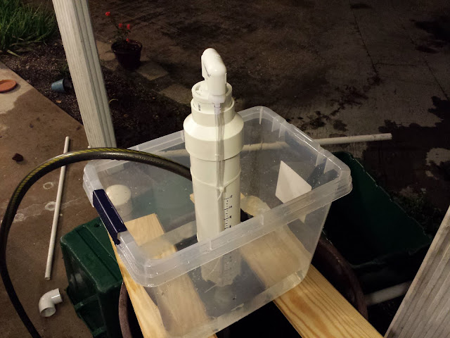
The snorkel test bell assembly.


Bell Water Level Observations

My snorkel bell rises quite high above the top of the standpipe.  The siphon had no problem starting, given sufficient flow - more on that later.  The interesting thing I noticed was that after the siphon started, the water level in the snorkel rose by at least 1", usually 2", and in the case of using 3/4" drain pipe it rose by over 4"!  This level would usually slowly drop as the water level in the source reservoir was depleted.  The informal relation seemed to be: the faster the siphon, the higher the level reading on the snorkel.

Compared to the 1" drain pipe, the 3/4" drain pipe appeared to deliver significantly more suction once siphoning began.  I had marked my bell with inch indicators up to 11", but the water level in the snorkel tube quickly shot above where the 12" would have been.  All 1" pipe tests delivered consistent results: snorkel level rose by about 1.5" from the top of the standpipe, and drain times were consistent.

It was also interesting to watch the water level shoot up once the siphon started in earnest, and to drop as it was breaking.   I was able to observe the transition from spillover to drain with ease.  Another interesting test would be to verify if the water level in the snorkel matches that inside the bell.

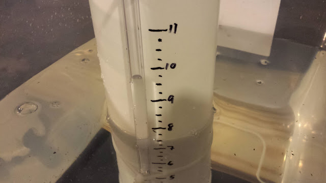
Siphon in action: Note that the level of the tank is around 7.5", whereas the water level in the siphon appears to be nearly 10"

Slow Fill Observations

For the slow-fill tests, I rigged the supply to provide approximately 0.0358 cubic centimeters per second of water.  This figure was calculated based on observing the rise of the water in the tank and calculating it against the estimated tank geometry.  The drain was left at 30" of 3/4" pipe for all the tests.  I used the standard bell for all but the final test.

I first observed the standpipe without the bell, to ensure that the rate would not quickly flood the standpipe.  Having observed this, I replaced the bell and waited to see if the siphon would start.  It did not.  I then added the funnel back onto the standpipe.  The water seemed to flood into the standpipe a little bit better, but the rate was still much too slow to trigger a full siphon.

I added one 90-degree bend to the bottom of the standpipe, but it had no effect.  I added a second 90-degree, and finally it achieved siphon.  I repeated this test without the funnel, and came up with generally the same results.

Slow Fill Conclusions

Fill rate is key for siphon start.  I hypothesize that the fill rate must overcome the non-siphon drain rate in order to build a solid column of water in the pipe.  One the water column has been established, the siphon will start.

If the fill rate cannot be altered, then adding fittings to create back-pressure also works.  I did not use a trap-style drain configuration, as I prefer to let the bell breathe while the tank fills.  I am also not yet convinced that the trap is superior to simply two downward-trending bends.  The two 90-degree bends - added back-to-back to the very end of the drain - added sufficient back-pressure in my experiments.  They also did not immediately appear to harm siphon drain rates.

We must realize that the siphon is a dynamic system and governed by flow rates.  As such, the addition of snorkels, bends, reducers, etc, to "fine tune" the siphon will work only so long as the flow rates are appropriate.  In other words, these things do not guarantee a better (or even a functional) siphon.  You are, in effect, simply moving numbers around.

The standpipe funnel also does not necessarily yield a better siphon, though I suspect it did allow the siphon to trip faster, moving from spillover to drain much quicker than with the straight, unadorned standpipe.  This is, after all, the reason people claim to employ a funnel on their standpipes.

In future experiments, I would like to examine the rates of inflow and outflow, to understand better how the addition of back-pressure solves siphon-start problems.  I would also be curious to see if the drain pipe length has an effect on siphon-start; in all my slow-start tests, I kept the drain pipe length constant.  Finally, it would be interesting to see if the water level inside the bell is an indicator of the rate of drain.

In no cases did the 1/8" emergency drain hole in the standpipe inhibit siphon operation or tank fill.  

All Drain Test Results

Below are the results from all the tests.  The last two columns are the calculated cubic centimeters per second of drain rate, and the calculated time it should have taken for draining to complete.  As can be seen, the wide variability in the results suggest further testing.  The 1" tests are also curious, in that they were extremely consistent and always significantly longer than the calculated times.  I suspect the reason for this is the 3/4" standpipe, and/or the bushing to go from 3/4" to 1" pipe.  I plan on performing additional tests using 1" standpipe, once I have a 1" bulkhead fitting.


3/4" Diameter Drain Pipe Tests
Test #lengthdrain time (seconds)calc cm3/scalc t
1044n/an/a
21126665.9329.90401379
328211,062.4618.74333258
91321723.9427.50769186
107.526531.2337.48666515
1130191,099.7518.10777959
1630221,099.7518.10777959
17 - no funnel30151,099.7518.10777959
1" Diameter Drain Pipe Tests
Test #lengthdrain time (seconds)calc cm3/scalc t
4644874.3522.77575217
512401,236.5216.10488881
6a30201,955.1110.18562602
6b30411,955.1110.18562602
7a - snorkel12361,236.5216.10488881
7b - snorkel12361,236.5216.10488881
7c - snorkel12361,236.5216.10488881
7d - snorkel12351,236.5216.10488881
8635874.3522.77575217