Showing posts with label siphon physics. Show all posts

2016-05-19

Production Siphon Experiment 2, and (Dis)regarding the Venturi Effect

After the dismal failure of my own damn reasoning, I worked on some revisions.  The target drain pipe size for the system will be 1.25" diameter.  I performed a test with this pipe, plus some 0.75" pipe to test some more relay siphon ideas.

The basic configuration I used was 1.25" for the below-bed siphon and drain pipe, but 2" for the standpipe.  This was partly on a whim.  I also experimented with a 1.25" standpipe.  The 2" worked significantly better, especially draining into the 1.25" lower siphon pipe.  It was as though I had simply moved the "funnel" that is commonly used in other configurations down to below the grow-bed.  I suspect the funnel action here really has nothing to do with the Venturi effect.  More on that below.

During the tests, I ran the water pump and cycled water between my test tank (a 20 gallon rubber-like plastic container I picked up for cheap) and a makeshift sump tank (a sufficiently large galvanized tub - from whence I bought it, I have no idea).  This provided a great opportunity to both test the pump at the likely head-height, in the production plumbing, and to save some water.

The 1.25" standpipe produced a very undesirable result: as water spilled into it, it formed a vortex which was maintained indefinitely.  The vortex evidently allowed sufficient water to leave the tank, and prevented siphon formation.  The 2" standpipe did not appear to suffer from this problem, and worked repeatedly without fail.

Apropos: my current bell is a 6" diameter PVC pipe, covered with plastic kitchen wrap and "sealed" with tape.  The wrap provides a sort of window into the inner-workings of the siphon.  My next available bell size is 3", which is too small to work with the 2" pipe and adapters.  I am hoping that 4" pipe will offer sufficing inside diameter.  The store does not seem to carry 5".

While watching the 2" pipe, I noticed that the flood of water down to the reducer fitting caused enough turbulence and sufficient restriction of flow for a decent blockade of water to accumulate, and thus the siphon would shortly follow.  I decided to try relaying in the 3/4" pipe I had installed in the same tub.  I used a 1.5" wye fitting, normally used for waste-water collection, and (due to a lack of 3/4" fittings) drove the 1.25" plumbing into the wye at 45 degrees.  The 3/4" pipe went straight down into the fitting, and the exit was directly below.  Appropriate adapters were used to deal with the size differences.  The exit piping was unfortunately a little too short: it ran straight into the sump as I tried to lengthen it.

Unfortunately, it didn't work.  The key problem was that there was simply too much turbulence at and after the wye for a good seal to form.  Even when the 3/4" standpipe was cut so that it was very close in height to the 2" standpipe, there was insufficient suction to start the 3/4" pipe.  I suspect this issue could be averted if the 3/4" was upstream from the 2", and the 1.25" pipe had sufficient horizontal length downstream of the 2" standpipe to ensure a good blockade of water.  I plan to retest, using the other 2" bulkhead fitting I have, once I have some 4" pipe.

Regarding Venturi

I am beginning to suspect that at the pressures and water velocities we're dealing with, the Venturi Effect is a negligible effect at best when we examine the funnel-style standpipe.  I'd like to propose another hypothesis: mass of water.  Let's suppose we have a 5" length of 2" diameter standpipe.  Water begins to flow over the top circumference and down the inside faces of the pipe.  Let's assume the water flowing down is 0.1" in thickness.  Let's freeze this scene as the water reaches the bottom of the standpipe (which is also the top of the 1.25" siphon drain).  For a 2" pipe and 5" of length, that's about 3 cubic inches of water.  Were we considering the same 0.1" thickness of water inside the 1.25" pipe alone, that would equate to about 1.8 cubic inches of water.  In other words, the larger standpipe provides a deluge by virtue of its geometry alone.

Dividing the 2" pipe's low volume of water by the 1.25" pipe's cross-sectional area gives us the result that the same volume of water would occupy 2.43" linear inches of the 1.25" pipe.  This, I believe, is the reason the siphon starts so easily with this configuration: that much water flooding the pipe is significantly more than a 1.25" standpipe would have supplied, thus a water blockade can form and induce a siphon.

The picture here attempts to illustrate the example from above.  The siphon is in red (2" standpipe, 1.25" drain), water is in blue.  The drawing is to scale.  The water on either side of the standpipe represents 0.1" of thickness.   Realize that the water is actually coming down around the entire circumference of the standpipe opening, and so is much more voluminous than what I can easily illustrate.  The water shown leaving the drain pipe (which is pointing down) is the equivalent volume as what is entering the standpipe.  It, too, is to scale.  As you can see, a relatively small volume of incoming water becomes a relatively large volume of draining water, and should saturate the pipe volume sufficiently to start the siphon.

Were we to use two 2" pipes, or two 1.25" pipes (that is, the same size between the standpipe and the drain), we must then hope that the water level continues to rise sufficiently to eventually saturate the siphon.  In the meantime, there would be physically little to stop the water from simply draining through without accumulating.  Thus, I suspect the Venturi effect is of little value here, and that the geometry of the pipes provides the most potential benefit.


2016-05-15

Progress, and a Failed Experiment

Today I was able to procure many additional materials: plywood, polystyrene panels, 2x4s and 4x4s, plus some plumbing supplies for further experiments.  I assembled the three grow-bed support frames.  I had to obtain a larger container to carry out the siphon experiments.

As I had mentioned in my last post, I had a crazy idea:

A miserable failure - do not repeat it!!
Yes, this is a two-stage inside the same bell.  IT DOES NOT WORK.  This is why I take notes on these things...it's just too bad I didn't actually re-read them before attempting this hair-brained idea.

Why does it fail?  The small red pipe feeds directly into the large main pipe.  There is no way enough water can flow into that massive blue down-pipe to form a siphon, therefore the siphon simply never forms.  What made the original 2-stage experiment successful was that the starter siphon formed a full and fast siphon. With the additional water being pumped into the larger out-piping, there was sufficient volume to start the larger siphon.

That is not the case with the above illustration.  What you see above is simply a slow flow into a very large pipe, which would happen even without that extra red pipe sticking out the side.  Without an actual siphon forming with the smaller pipe, there is insufficient water flow to trigger the main siphon.

Some other bad points about the above design: it's huge, it requires a very large diameter bell (which equates to an even larger media guard - bleh), it doesn't work (as previously mentioned), it requires many more fittings than its worth, and so on.  I will be trying some more experiments soon.  Namely, I want to see if a 3/4" starter siphon will trigger a 2" main siphon.  If it does, my next experiment will test two 2" main siphons with the 3/4 starter.  I can also modify the diameter of the out-piping, to help ensure the flow is sufficient to trip the other siphons.  The catch is that the smaller the out-pipe, the less flow it can handle, so there may cease to be a reason to run 2" siphons.

2016-01-21

Relay Siphon - Theory and Practice

I have done some additional experiments with the relay siphon, and am pleased with the results.  Using a 1/2" diameter control siphon, I was able to start the main siphon in a very short period of time.

Here are some numbers:

Relay Siphon Test
1" drain, 3/4" main standpipe, 1/2" control standpipe
Fill Rate0.01449275362in/sec
time to 1/2" spillover195sec
height at 1/2" spillover5.326086957inches
volume at spillover13257.96562cm3
main siphon start time14seconds
main drain time17seconds
main drain rate779.8803306cm3 / sec


Most of these numbers are approximates, since the timer is human-operated and the measurements are not exact.  What we can be certain of is that the relay does actually work.  The 1/2" spillover height is the water level where the 1/2" control standpipe begins experiencing water flow.  The siphon start time is the time between when the control siphon starts and the main siphon starts - that is, the control siphon operated for 14 seconds before the main siphon began to pull water down.  From the time the main siphon operated to the time it finished was 17 seconds.  Note that during this time, the control siphon had lowered the water level as well, but by only a very small amount.

Here's a picture of one of the other relay tests:

The presence of the trap does not necessarily help nor hurt the control siphon.  It does cause air to be trapped in the control bell, so the water level does rise quite a bit higher than without the trap.  The above picture shows the 1/2" control (left) feeding into the 3/4" tee from the main (right), into a 90 and down a 3/4" drain pipe.  The drain rate on this setup seemed slower than the 1" drain pipe, but unfortunately I didn't have time to pull any timing numbers.  But again, this test was primarily about the function of the relay.

To ensure the water level was slow enough not to trip the 3/4" standpipe, I capped the control pipe and let the water rise.  As expected, there was insufficient flow and insufficient back-pressure to trigger the 3/4" siphon.  Uncapping the 1/2" standpipe caused a flood of water into the drain, which then triggered the main siphon, thus demonstrating that sufficient flow from the control was all that was necessary to induce the main siphon.

Replacing the bell on the control siphon allowed it to function as designed: by starting its siphon at sufficient water height, and providing sufficient flow via siphon-action alone to trigger the main siphon.  I was able to watch the main siphon start using my snorkel bell (described in an earlier post).  It would start several seconds after the control started full siphoning.

While a single large main siphon will certainly draw water out of a grow-bed quickly, I could see this mechanism also finding use in long grow-beds where the risk of poor circulation may be significant.  You should, in theory, be able to tee-in a number of main siphons and have them trigger off of one control.  Once one of the main siphons starts, the flow should be great enough to start any remaining main siphons that did not start from the control flow alone.  I'd like to experiment with this in the future.

All this fast draining potential has me asking another question, however - one that I don't readily see much information on in the literature I've read to-date: how long should plant roots be exposed to water before the grow-bed is drained (or air after it has drained)?  If it takes an half hour to fill the bed, and 60 seconds to drain it, the roots may be exposed to air for at least 15 minutes before the water level is high enough to touch their tips.  I'm hoping there is other literature out there, especially among the hydroponics community, that addresses this.  The closest thing I think I've seen to a number is with the timer-based flood-and-drain systems: 15 minutes of fill time, 45 minutes of drain-and-empty time.

More work to do!

2016-01-18

Two-stage (Relay) Bell Siphons

I was considering today how to deal with the flow-rate problem for siphon-start, when an idea struck me.  I suspect someone has thought of this before, but a short web search didn't turn up anything fruitful.  There is one fellow I know of that does something similar: he has multiple large grow-beds on a slope, and synchronizes their draining using a 55-gallon drum.  There's a video on YouTube about it.

How about for smaller grow operations?  Let's suppose you have a fairly large grow bed.  First problem: the bed will fill very slowly, so the rate of height-gain of the water may not be sufficient to trip a large-diameter siphon.  Second problem: you want the bed to drain quickly, so you need a large diameter siphon.

The theory of operation is similar to that of a relay: we use a small current to trigger a large current.

The image to the right shows two siphons feeding into the same drain.  The smaller siphon (green) is the control siphon.  The larger (red) is the main siphon. The operation is simple: the control siphon trips quickly, thanks to its small diameter, and starts a rapid flow of water through the drain pipe.  This flow creates a vacuum that pulls water up into the main siphon, thus starting it.  Once the main siphon starts, both siphons will operate until water has been drawn down to the highest intake hole - or down to the bottom of the snorkel tube, if so equipped.

Note that the drawing I have here is not to scale, nor is this configuration of pipes necessarily a good one.  I also did not test the configuration in the drawing.  I did, however, test something very similar:

Two-stage, or relay, bell siphon test
The image shows my test apparatus, with some peculiar plumbing.  The drain for the bell siphon (inside the tank) runs into a 90, which then heads into a tee fitting. The tee sports the control tube (from the top), and a drain out the bottom.  The drain is further fitted with another 90 and some extra pipe, to provide back-pressure.  I was able to start the siphon without the extra 90 and pipe, but it required a high rate of flow through the control.

To test, I filled the tank with water up to the 6" mark.  The main standpipe is 8" tall.  The bell was then placed on top of the standpipe.  I used a hose-to-slip fitting to attach the garden hose to the control pipe.  I was then able to control the rate of flow through the control pipe at the spigot.  With a very low flow rate, the siphon tripped after about 10 or so seconds, which I suspect to be the time it required to pull sufficient vacuum on the main siphon.

The pipes in the image above are a mix of 3/4" and 1", only because I had no 3/4" tees available.  Ideally, the control pipe should be smaller than the main pipe, and of a consistent diameter.  The low rate of flow I was able to use on the control pipe suggests that were the control itself a bell siphon, it would very readily trip the main siphon into action, since a bell siphon would generate a significantly greater rate of flow.  As an added bonus, having two siphons in operation at the same time should produce faster drain rates as well.  And with sufficiently high drain rate, we may avoid the siphon-stop problem.

I would ensure the main standpipe rises 1/2" above the control standpipe, so that there is no chance of the main pipe leaching water and prohibiting the siphon from starting.  It would be good not to go too high, though, since the vacuum generated by the control pipe may not be great enough to pull the water more than 1 or 2 inches up into the main siphon's bell.  I'd like to test this further, using a single bucket, some 1/2" pipe for the control, and upwards of 2" pipe for the main.  2" is probably overkill, but it would be nice to know it works.

One other possibility is to have the control standpipe and the main standpipe together in the same bell (pictured at right).  This would require a large diameter bell, but it would also allow you to use a single snorkel to break the siphon - if so desired.  It would require two bulkhead fittings in close proximity.

Again, the pipes in my drawings and on my test assembly are not ideal; there are probably many configurations possible that would achieve the same effect.

One last note:  it may also be possible - but is, as of yet, unconfirmed - that the control pipe need not necessarily be housed inside a bell.  Once the main siphon starts, the operation of the system reverses: instead of the control pipe pulling vacuum on the main pipe, the main pipe instead pulls vacuum on the control.  So long as the main siphon assembly is operating properly, it ought to be possible to have the control open to the air without losing siphon.  All things being equal, however, I think I'd prefer housing the control be in a bell for the reasons stated above.

Siphon Testing - Round 2, Brief Findings

The standpipe and funnel assembly
I ran several tests on my experimental siphon, trying different diameter drain pipes and different lengths.  I also tested slow-fill, to determine whether or not the standpipe funnel actually helps.

Effects Drain Pipe Diameter and Length on Drain Times


The standpipe is 3/4" in diameter.  I ran several tests with various configurations (with and without snorkel, with and without the standpipe funnel).  Unfortunately I could only run one or two tests per series, so please take these results with a grain of salt...

As you can see on the chart above, the 3/4" drain pipe length appears to affect drain times fairly predictably.  Unfortunately the drain rate increases were not as high as I was hoping them to be.  The first test (left-most dot) is without any additional drain pipe.  The X axis is pipe length, the Y axis is the seconds to drain - that is, the time from siphon-start to the siphon-end burp.

The fastest drain time was recorded while testing without the funnel in place.  I only ran one test of that sort, however, so that result might be an outlier.  I noticed that in only one or two tests the drain rate would be extremely fast, but in the remainder of tests it seemed to hold fairly constant.

For the next series of tests, I used a bushing to convert to 1" after the bulkhead fitting.   The idea for this was to reduce static pressure and allow the water to flow faster.  Thus, 1" drain pipe would be used.  As this was larger than 3/4", technically it would have operated at slightly higher pressure.
The majority of the 30" tests were done with a snorkel bell.  The snorkel was used primarily to watch the pressure inside the bell.  The most important things to note here are that the drain rate remained constant for most of the tests, between 35 and 40 seconds for nearly every test, and seemingly regardless of drain length.  Again, in the chart above, the X axis is for length, the Y axis for drain time (in seconds).

I would hypothesize, based on these data, that the ideal solution is to maintain a constant pipe diameter throughout the bell siphon.

The snorkel test bell assembly.


Bell Water Level Observations

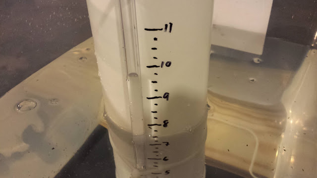
My snorkel bell rises quite high above the top of the standpipe.  The siphon had no problem starting, given sufficient flow - more on that later.  The interesting thing I noticed was that after the siphon started, the water level in the snorkel rose by at least 1", usually 2", and in the case of using 3/4" drain pipe it rose by over 4"!  This level would usually slowly drop as the water level in the source reservoir was depleted.  The informal relation seemed to be: the faster the siphon, the higher the level reading on the snorkel.

Compared to the 1" drain pipe, the 3/4" drain pipe appeared to deliver significantly more suction once siphoning began.  I had marked my bell with inch indicators up to 11", but the water level in the snorkel tube quickly shot above where the 12" would have been.  All 1" pipe tests delivered consistent results: snorkel level rose by about 1.5" from the top of the standpipe, and drain times were consistent.

It was also interesting to watch the water level shoot up once the siphon started in earnest, and to drop as it was breaking.   I was able to observe the transition from spillover to drain with ease.  Another interesting test would be to verify if the water level in the snorkel matches that inside the bell.

Siphon in action: Note that the level of the tank is around 7.5", whereas the water level in the siphon appears to be nearly 10"

Slow Fill Observations

For the slow-fill tests, I rigged the supply to provide approximately 0.0358 cubic centimeters per second of water.  This figure was calculated based on observing the rise of the water in the tank and calculating it against the estimated tank geometry.  The drain was left at 30" of 3/4" pipe for all the tests.  I used the standard bell for all but the final test.

I first observed the standpipe without the bell, to ensure that the rate would not quickly flood the standpipe.  Having observed this, I replaced the bell and waited to see if the siphon would start.  It did not.  I then added the funnel back onto the standpipe.  The water seemed to flood into the standpipe a little bit better, but the rate was still much too slow to trigger a full siphon.

I added one 90-degree bend to the bottom of the standpipe, but it had no effect.  I added a second 90-degree, and finally it achieved siphon.  I repeated this test without the funnel, and came up with generally the same results.

Slow Fill Conclusions

Fill rate is key for siphon start.  I hypothesize that the fill rate must overcome the non-siphon drain rate in order to build a solid column of water in the pipe.  One the water column has been established, the siphon will start.

If the fill rate cannot be altered, then adding fittings to create back-pressure also works.  I did not use a trap-style drain configuration, as I prefer to let the bell breathe while the tank fills.  I am also not yet convinced that the trap is superior to simply two downward-trending bends.  The two 90-degree bends - added back-to-back to the very end of the drain - added sufficient back-pressure in my experiments.  They also did not immediately appear to harm siphon drain rates.

We must realize that the siphon is a dynamic system and governed by flow rates.  As such, the addition of snorkels, bends, reducers, etc, to "fine tune" the siphon will work only so long as the flow rates are appropriate.  In other words, these things do not guarantee a better (or even a functional) siphon.  You are, in effect, simply moving numbers around.

The standpipe funnel also does not necessarily yield a better siphon, though I suspect it did allow the siphon to trip faster, moving from spillover to drain much quicker than with the straight, unadorned standpipe.  This is, after all, the reason people claim to employ a funnel on their standpipes.

In future experiments, I would like to examine the rates of inflow and outflow, to understand better how the addition of back-pressure solves siphon-start problems.  I would also be curious to see if the drain pipe length has an effect on siphon-start; in all my slow-start tests, I kept the drain pipe length constant.  Finally, it would be interesting to see if the water level inside the bell is an indicator of the rate of drain.

In no cases did the 1/8" emergency drain hole in the standpipe inhibit siphon operation or tank fill.  

All Drain Test Results

Below are the results from all the tests.  The last two columns are the calculated cubic centimeters per second of drain rate, and the calculated time it should have taken for draining to complete.  As can be seen, the wide variability in the results suggest further testing.  The 1" tests are also curious, in that they were extremely consistent and always significantly longer than the calculated times.  I suspect the reason for this is the 3/4" standpipe, and/or the bushing to go from 3/4" to 1" pipe.  I plan on performing additional tests using 1" standpipe, once I have a 1" bulkhead fitting.


3/4" Diameter Drain Pipe Tests
Test #lengthdrain time (seconds)calc cm3/scalc t
1044n/an/a
21126665.9329.90401379
328211,062.4618.74333258
91321723.9427.50769186
107.526531.2337.48666515
1130191,099.7518.10777959
1630221,099.7518.10777959
17 - no funnel30151,099.7518.10777959
1" Diameter Drain Pipe Tests
Test #lengthdrain time (seconds)calc cm3/scalc t
4644874.3522.77575217
512401,236.5216.10488881
6a30201,955.1110.18562602
6b30411,955.1110.18562602
7a - snorkel12361,236.5216.10488881
7b - snorkel12361,236.5216.10488881
7c - snorkel12361,236.5216.10488881
7d - snorkel12351,236.5216.10488881
8635874.3522.77575217

2016-01-12

Siphon Physics - Bell Heights and Drain Lengths

I have done some work on the bell siphon, and determined some interesting things:

The height of the bell does NOT seem to matter for siphon start.

To test this, I used a bell that was literally twice the length of the original, so that there was a very large air-column present.  Not only did the siphon start on schedule, but it also burped just as the original bell had.  I'd like to see this happen with a transparent bell, so as to see where the water level sits during operation.

Note that a siphon can operate with a gap between the drain and the supply; this is a "drip siphon."  It may be likely that any sufficiently large bell will always contain residual air during operation.  Whether or not this impacts the drain rate has not yet been determined.

Drain length DOES determine siphon rate.

To test, I ran a cycle with a short drain, then lengthened the drain pipe significantly.  The drain was a straight drop, down to a couple of 90-degree bends for back-pressure.  I stopped filling the basin once the water started spilling over.  While I have yet to go back over the videos and time the actual drains, I believe the longer pipe does in fact contribute faster drain rate. 

UPDATE: I determined from watching my videos that the short drain test emptied in approximate 61 seconds, whereas the long drain test emptied in approximately 47 seconds.  I timed from when the water started spilling over to when the bell finally burped.  According to calculations, the best possible increase in drain rate should have resulted in a 20-second decrease in drain time; I achieved 14 seconds decrease in drain time.  
I suspect the other 6 seconds may be due to lack of sufficient intake (I have perhaps 0.9 square inches of intake area available, turbulence notwithstanding), coupled with flow restrictions from the double-90's, and the reduced flow area inside the bell where the reducer is located.  Also, the imperfect seal between the bell tube and dome allows for air to intrude, and may be weakening the siphon rate.  A more careful examination of these variables will be required.

The math backs this up: according to Bernoulli's equations, the length of the drain pipe alone determines the siphon rate - up to the maximum possible rate, which is determined by another portion of the siphon and associated pressures and densities.  As such, doubling the drain's length will increase the siphon rate by a factor of roughly 1.4.  Example:  A 5" long drain on a siphon made with 3/4" pipe will drain at 449 cm3/sec.  That siphon with a 10" drain will operate at 635 cm3/sec, other factors notwithstanding.

The lesson should be clear: maximize the length of your drain pipe.

Snorkel Test #1

I also built a basic snorkel and tested it.  One interesting thing to note: the water level in the snorkel never went higher than what I would suppose to be the level of the water in the siphon itself.  Once the snorkel finally received air, the water was sucked up into the top of the bell and the siphon was broken.

I assembled my snorkel from a 3" to 2" reducer, then a 2" to 1", which I further reduced to 1/2" and then made two 90-degree turns.  To this I screwed in a pipe barb and attached a piece of 1/4" vinyl tubing.  The tubing is not yet secured to the bell.  I am anxious to try the inverted cup method, and would like to see how it operates with the cup attached to the side of the siphon.  I would also be curious to see if 1/2" PVC could be used instead of the vinyl tubing.